Menu

Exp. 1: Inverse Definite Minimum Time (IDMT) Over Current Relay


Aim of experiment

To study the Operation of an Inverse Definite Minimum Time (IDMT) Over Current Relay and plot the inverse time current characteristics of IDMT over current.


About experiment


Performance Objectives:

On completion of this experiment, participants will be able to understand working of numerical over current relay and plot its inverse time/current characteristics with definite minimum time


1.To plot inverse definite minimum time characteristics of numerical over current relay.

2.To perform experiment on definite / instantaneous mode setting of the relay.


Theory


Inverse Definite Minimum Time (I.D.M.T) Characteristics:

When a protection element is programmed as an inverse time over current (OC) element, the trip relay operates if, the input signal exceeds the set threshold OC setting by 1.2 (typical) times. The operating time of the trip relay is a function of the relative value of the relay current with reference to the set threshold current value; the variation in curve is brought about by constants K and a.

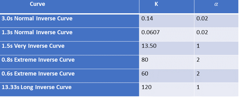
There are six inverse time operating characteristics


  1. 1. 3.0s Normal Inverse Curve
  2. 2. 1.3s Normal Inverse Curve
  3. 3. 1.5s Very Inverse Curve
  4. 4. 0.8s Extreme Inverse Curve
  5. 5. 0.6s Extreme Inverse Curve
  6. 6. 13.3s Long Inverse Curve


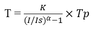
For timing calculations, we use the following equation,

Where,

I = Fault current
Is = Fault current level set in the relay
T = Operating time in secs.
Tp = Time Multiplier Setting (TMS)
K and a = Curve constants


Table 1: Curve constant
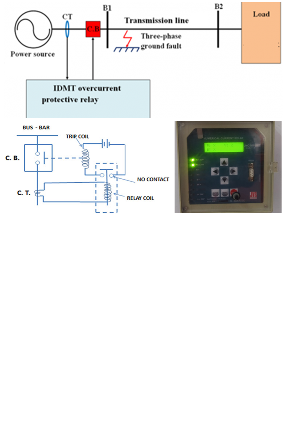
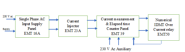


Current Setting:

The current above which an over current operate can be set. Suppose that a relay is set at 5A. It will then operate if the current exceeds 5A. Below 5A, the relay will not operate. In this numerical type of relay, there is phase OC (IDMT) setting from 2% to 250% in step of 2% i.e., for 5A relay setting PH>(IDMT) setting will be 0.1A to 12.5A using keyboard setting. An over current relay which is used for phase to phase fault protection, can be set at 2% to 250% of the rated current in steps of 2%. The usual current rating of this relay is programmable as 1A or 5A.

If the time-current curves are drawn, taking current in amperes on the X-axis, there will be one graph for each setting of the relay. To avoid this complex situation, the plug setting multipliers (PSM) are taken on X-axis. The actual r.m.s. current flowing in the relay expressed as a multiple of the setting current (pick up current) is known as the plug setting multiplier (PSM). Suppose, the rating of a relay is 5A and it is set at 200%, i.e. at 10A. If the current flowing through relay (secondary fault current) is 100A, then the plug setting multiplier will be 10. Against each multiplier, the manufacturer specifies trip time. In this case for PSM 10, relay shall trip @3sec which we can verify by experiment. The PSM can be expressed as


Trip Time Setting: 

The operating time of the relay can be set at a desired value. In this relay TMSvalues can be set from 0.02 to 1.0 in step of 0.01 by using front keyboard.
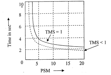

IDMT Curve: 

While plotting the time current characteristics, if PSM is plotted on the X-axis, there will be one curve for each trip time setting (TMS) of the relay. The curves are generally plotted as shown below. From ratio of secondary fault current to relay current setting, we get PSM, then follow particular curve for set TMS to get trip time in seconds on Y-axis.


Figure 1: IDMT curve


From the figure the operating / trip time, when plug (current) setting multiplier is 10 and the time multiplier is set to 1, is 3 seconds


Procedure


Equipment Used:


  1. 1. Single Phase AC Input Supply panel (EMT 16A)
  2. 2. Current Injector (EMT 23 A)
  3. 3. Current Measurement and Elapse Time Counter panel (EMT 39)
  4. 4. Numerical IDMT Over Current relay (EMT 50)


Block Diagram:


The Block Diagram of Numerical IDMT Relay is given below:


Procedure:


Make wiring sequence in the experimental setup as per schedule given below:


  1. 1. Make the wiring sequence as per wiring schedule. Keep the dimmer at minimum position on EMT-
        23A panel.

  2. 2. Keep bypass switch open (left hand side) on EMT-39 panel.

  3. 3. In the RYB three phase numeric over current relay (OCR) circuit on EMT-50 panel, we are using only
        one phase, say 'R'.


Quiz


  1. 1. IDMT relays are used to protect the power transformers against

  2. A) External short-circuit
    B) Overloads
    C) Internal short-circuits
    D) Both A and B

    Answer. D

  3. 2. A CT is connected in ___________________ with the line.

  4. A) series.
    B) across.
    C) not connected.
    D) both A and B.

    Answer. A

  5. 3. In the relay coil which is used?

  6. A) Current transformer.
    B) Potential transformer.
    C) Power transformer.
    D) Instrument transformer.

    Answer. A

  7. 4. What type of back up protection is used for alternators?

  8. A) IDMT relay.
    B) Buchholz relay.
    C) Mho relay.
    D) Impedance relay.

    Answer. A

  9. 5. Differential relays are used for protection of equipment against

  10. A) Internal faults.
    B) Overcurrent.
    C) reverse current.
    D) reverse power.

    Answer. A

  11. 6. Both voltage and current signals are required for

  12. A) A plain over current relay.
    B) A differential relay.
    C) A directional relay.
    D) A biased differential relay.

    Answer. C

  13. 7. In an inverse definite minimum time, electromagnetic type over-current relay, the minimum time feature is achieved because of


  14. A) saturation of the magnetic circuit.
    B) Proper mechanical design.
    C) Appropriate time-delay element.
    D. Electromagnetic damping.

    Answer. A

  15. 8. If the fault occurs near the relay, the V/I ratio will be

  16. A) Lower than that of if the fault occurs away from the relay.
    B) Constant for all distances.
    C) Higher than that of the fault occurs away from the relay.
    D) None of the above.

    Answer. A

  17. 9. The relay with inverse time is:

  18. A) Directly proportional to the square of fault current.
    B) Direct proportional to the of fault current.
    C) Inversely proportional to the of fault current.
    D) Inversely proportional to the square of fault current.

    Answer. C

  19. 10. An efficient and well-designed protective relaying should have

  20. A) Good selectivity and reliability.
    B) Economy and simplicity.
    C) High speed and selectivity.
    D) All the above.

    Answer. D

  21. 11. When the fault current is 2000 A, for a relay setting of 50% with CT ratio 500/5, the plug setting
          multiplier will be

  22. A) 16.
    B) 12.
    C) 4.
    D) 8.

    Answer. D


Tutorial


References


  1. 1. Power System Protection by ANDERSON P.M., JOHN WILEY


  2. 2. Fundamentals of Power System Protection by Paithankar Y.G, PHI


  3. 3. Practical Power System Protection (Practical Professional Books), by Leslie Hewitson, Mark Brown,
        Ramesh Balakrishnan, Kindle Edition


Live Support


×